
Soldering is the technique of bonding two metals together using a solder alloy, which is very important for creating dependable connections in electronics. On a PCB, the solder melts and sticks to the metal, keeping the components together. In order to avoid flaws such as cold solder joints, proper soldering is necessary for the performance and durability of electronic devices.
Poor soldering is the cause of approximately 70% of electronic failures, according to current research. Weak connections in electronic components can result from improper solder melting, which is known as a cold solder joint. This flaw greatly impacts electronic gadget quality and dependability. Intermittent connections, device problems, and total circuit failures are typical signs of cold solder junctions.
Electronic device problems such as shimmering screens, sluggish controls, and unpredictable behaviour might be attributed to these weak joints. It helps to identify and steer clear of cold solder junctions if you want your electronics to last a long time and function well. Check out how to keep the electronic assembly reliable and efficient by fixing this issue.
Key Highlights
- Soldering is the technique of bonding two metals together using a solder alloy, which is very important for creating dependable connections in electronics.
- Cold solder joints may occur due to poor soldering, weak connection, or poor junctions.
- You must preheat the soldering iron to the appropriate temperature, use premium solder, and clean the PCB layers to avoid cold solder joints.
- There are three types of solder joints: cracked solder joints, dry solder joints, and cold solder joints.
- You can conduct visual inspection, thermal imaging, and use multimeters to test solder joints.
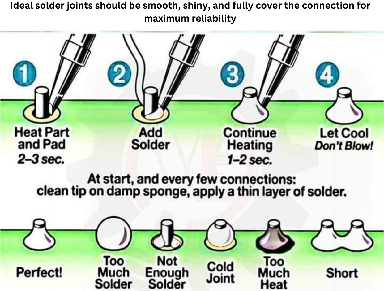
- An idle solder joint will have a smooth surface, shiny finish, complete wetting, appropriate flow, and clear connections
What are Cold Solder Joints ?
A fault known as a "cold solder joint" arises when the solder does not melt completely, leaving electrical components with a weak connection. A cold solder joint seems uneven and dingy in contrast to a good solder joint, which is glossy, smooth, and homogeneous in appearance. The operation and dependability of electronic devices may be affected by these sporadic or total electrical failures brought on by this inadequate bonding.
Since solder joints offer strong, solid connections that can take a variety of loads and environmental conditions, maintaining good solder joints is important for maintaining the functionality and lifespan of electronics. For the purpose of quality control, cold solder connections must be identified and avoided.
The Risks
- Intermittent connections bring on random breakdowns and inconsistent performance.
- Device malfunctions might result in unplanned stops or malfunctions while the device is operating.
- Devices experiencing complete circuit failures are rendered completely non-functional.
Common Failures
- Flickering screens disrupt the user experience and suggest underlying connectivity concerns.
- Device usability and functionality can be impeded by inoperable interfaces.
- Erratic behaviour ruins a device's dependability by causing unexpected performance.
Defects where the solder melts improperly and forms a weak connection, are known as cold solder joints. A cold solder junction appears uneven and dull in contrast to a good solder joint, which is smooth and bright, resulting in weak and unreliable connections. Intermittent connections, device problems, and total circuit failures may result from this problem.
In particular, gadgets like laptops, cell phones, medical devices, and aeronautical instruments are susceptible to these issues. The longevity and dependability of electronic devices depend on robust, solid solder junctions, which offer protection against potential dangers and failures.
What are the Causes of Cold Solder Joints?
Soldering is important in the engineering and industrial industries because of its effectiveness and adaptability. Using this popular method, two components are joined by melting a filler metal. Its appeal is a result of its capacity to establish solid, dependable connections without requiring the melting of the device's actual functional components. Many typical problems can lead to cold solder junctions.
- Weak connections result from the solder not melting fully during the soldering operation due to insufficient heat.
- Poor junctions result from dirty PCB or component surfaces that prevent adequate solder adherence.
- Cold solder junctions can also result from improper soldering methods, such as using the incorrect kind of solder or not utilising enough flux.
These elements lead to inconsistent and perhaps unstable electrical connections by obstructing the solder's ability to flow uniformly and fully bond. It's important to use the right heat, clean surfaces, and practice to avoid cold solder junctions.
Environmental variables and poor supplies are two common reasons for cold solder connections. During the PCB fabrication process, environmental conditions such as dust or high humidity can contaminate surfaces, which can prevent effective solder adhesion. Subpar components, such as flux or solder, may not melt uniformly, damaging PCB layers and resulting in weak joints. Furthermore, partial connections may arise from the solder that does not melt entirely during the soldering process due to inadequate heat. Achieving dependable connections and preventing cold solder joints during PCB assembly requires using high-quality materials, keeping surfaces clean, and applying enough heat.
Tips on how to ensure proper heat application during soldering
Observe these guidelines to guarantee that the right amount of heat is applied when soldering.
- Set the soldering iron's temperature to the recommended level, usually approximately 350°C (662°F), depending on the type of solder being used.
- Maintaining effective heat transfer and avoiding contamination requires routine cleaning of the soldering iron tip.
- Heat both the component and the PCB component evenly so that the solder melts uniformly and forms a firm bond.
- A PCB component may be harmed by overheating, so be careful when using a solder.
- Everyone may reduce the possibility of cold solder junctions and create dependable, high-quality connections by managing these variables.
How to Identify Cold Solder Joints?
A quality solder joint will often have a glossy surface and a slightly concave shape. It should ideally have a 40–70 degree slant and not have an excessive amount of solder on it.
Visual characteristics of cold solder joints
Visual qualities are important in identifying cold solder connections.
- Look for solder connections that are dull, gritty, or broken. Cold solder junctions can look uneven and rough in comparison to a well-finished, polished joint.
- These flaws can be seen throughout the PCB fabrication process because they compromise the structural integrity of the PCB layers.
- A detailed examination of the PCB assembly can identify these problems, which frequently result in subpar electrical connections.
- It's possible to avoid cold solder junctions and guarantee dependable operation in the electrical components by closely monitoring your gadgets for these symptoms.
Common Signs of Cold Solder Joints on a Circuit Board
- Using a multimeter to measure resistance and continuity will help you locate cold solder junctions.
- Since cold joints frequently show greater resistance, it most likely has a cold joint if the reading (in non-resistor components) is higher than zero.
- To test the joint, switch the multimeter to continuity mode. If there isn't a beep, there may be a problem with the joint.
- On a circuit board, dull, gritty, or cracked looks are common indicators of cold solder junctions.
- These problems have the potential to disturb PCB layers and impair overall performance during the PCB fabrication and assembly process.
- Reliable solder connections are maintained through routine testing and inspection.
Effects of Cold Solder Joints
Electronic equipment may experience short- and long-term problems due to cold solder junctions.
- They frequently result in irregular connections in the short term, which might cause devices to malfunction or fail occasionally.
- These problems could interfere with PCB assembly and prevent it from working properly.
- Cold solder junctions have the potential to reduce a device's long-term dependability, which could result in total circuit failures and more serious harm to the PCB layers.
- Weak connections might eventually lead to wear and tear on the PCB construction process.
- Maintaining device performance and preventing these negative impacts require high-quality soldering.
- Cold solder junctions have resulted in significant real-world failures. For example, in a well-known case, cold solder connections impacting Wi-Fi chips caused intermittent connectivity troubles for smartphone manufacturers.
- Similarly, cold solder junctions broke vital avionics connections, leading to component failures in aerospace applications.
- These problems, which affected PCB layers and device dependability, resulted from errors in the PCB production and assembly process.
- The malfunctions above underscore the significance of superior soldering in averting such issues and maintaining resilient functionality and durability in electronic gadgets.
Early repair of cold solder junctions is essential to preventing these expensive and inconvenient consequences.
In electronics, cold solder connections can lead to severe issues. They frequently result in occasional or irregularly failing devices or abnormal functioning of the equipment. The weak joint's failure to establish a stable electrical channel is the root of this problem.
Cold solder junctions also cause an increase in resistance, which interferes with current flow and impairs the functionality of the device. These problems can eventually cause component failure when the weak connections deteriorate even more. Such flaws can jeopardise the overall reliability of the device and PCB layers during PCB assembly and manufacture. In order to avoid these negative impacts, proper soldering techniques are necessary.
How to Prevent Cold Solder Joints?
Check out these helpful ideas to avoid cold solder junctions.
- By preheating the soldering iron to the appropriate temperature and evenly heating the component and the PCB, It can ensure that the correct soldering procedures are used.
- For correct melting and adhesion, use premium solder and flux. To prevent contamination, clean the soldering iron tip on a regular basis to maintain equipment.
- After PCB manufacture and assembly, check and clean the PCB layers to get rid of oxidation and dust.
It is important to use high-quality flux and solder to achieve appropriate adherence and melting in order to prevent cold solder junctions. Weak connections may be the result of subpar materials. Maintaining clean surfaces is equally critical, as impurities such as oxidation or dust on the PCB layers might interfere with the correct adhesion of the solder.
A clean and well-prepared surface is essential for both PCB production and assembly. Cold solder joins can also be prevented by putting best practices into practice, such as providing professionals with adequate training and performing routine maintenance on soldering equipment, such as cleaning the soldering iron tip. You may guarantee more dependable and durable electronic connections by paying attention to these factors.
Best Practices for Technicians and Hobbyists to avoid Cold Solder Joints
The risk of cold solder junctions can be considerably decreased by providing technicians and enthusiasts with training and recommended practices. Give instruction on correct soldering methods, such as how to uniformly heat components and pads to guarantee that the solder melts completely. Maintaining clean and well-tinned soldering iron tips is one way to prevent contamination that might cause cold joints in soldering equipment.
To improve overall quality, incorporate these strategies into the PCB fabrication and assembly processes. To spot such problems early on and take appropriate action, conduct routine inspections and quality control checks. By putting an emphasis on these preventive steps and ongoing education, cold solder joints can be avoided by professionals and amateurs alike, resulting in more dependable and long-lasting electrical products.
Detecting and Testing for Cold Solder Joints
Learn the proper methods for testing and diagnosing cold solder junctions to keep your project moving forward and avoid costly delays.Finding cold solder junctions is essential to making sure electronic boards are reliable. Here are some techniques and tools you can use to find these problems.
Methods :
- Lighting and Magnification: To light up and enlarge the solder joints on the PCB, use a spotlight, magnifying glass, or microscope. This makes it easier for you to spot minute flaws.
- Verify Colour of Solder Joint: Check for a grainy or dingy look. Smooth, glossy solder connections are the hallmark of good soldering. Often, cold solder junctions are indicated by dull joints.
- Inspect Shape: Look at each joint's form. Concavity is the form of a correctly soldered junction. A joint may not have melted completely because of incorrect heating if it is distorted or lacks the right shape.
- Light Test: Using the magnifying lens, shine a torch through the joint. Should light be able to pass through, the joint is not properly bonded and could need to be repaired.
- Tilt Test: To see if any joints have partially detached from the base, tilt the board. For fear of damaging the board, keep an eye out for any solder leaks that can result in short circuits.
You need various tools like a microscope, magnifying glass, or spotlight for visual inspection.
Electrical Testing
a) Assessing Resistance
- Assign the Multimeter: Place the multimeter at 1000 ohms in resistance mode.
- Check Continuity: Connect the testing probes. A zero reading verifies that the multimeter is working.
- Test Joints: Attach one probe to the terminal of one component and the other to a solder joint. For components that are not resistors, the reading should always be zero. A possible cold joint is indicated by a value greater than zero.
b) Examining Continuity
- Put the device on Continuity Mode: Put the multimeter in continuity mode, and if the connection is strong, it should beep.
- Test Joints: Attach the test terminals to the solder joint's ends. In the event that there is no beep, the joint may be defective and require repair.
The quality and dependability of the PCB fabrication process, PCB layers, and PCB assembly can be maintained by combining these optical and electrical tests to identify and address cold solder connections efficiently.
The Basics of Soldering
In electronics, soldering is a necessary procedure that connects components to a PCB (Printed Circuit Board). Developing a dependable electrical connection between the component leads and the PCB layers is the primary objective. Solder is used in several forms; lead-based and lead-free solder are two of the varieties.
Lead-free solders, like SAC305, are used for safety and environmental reasons, whereas lead-based solders, like 60/40 tin-lead, are famous for their convenience. Solder wire, flux, and a soldering iron are among the tools used in soldering.
Important Steps for Getting a Good Solder Joint
- Preparation: A clean fabrication process, free of dust and oxidation on all surfaces are necessary. This facilitates correct solder application.
- Heating: Set the soldering iron's temperature to the proper level, which is typically about 350°C (662°F). Heat the PCB pad and component lead in equal amounts.
- Solder Application: Feed solder wire into the heated junction to apply solder. Permit it to circulate uniformly across the pad and component lead. Once the solder has cooled naturally, remove the soldering iron.
- Inspection: Provide the joint that has a glossy and smooth appearance. A healthy joint should be smooth and concave, without any fractures or lumps.
Common Soldering Issues and Their Fixes
- Cold solder joints: Usually the result of limited heat or low-quality solder, these seem drab and granular. To prevent this problem, use premium solder and flux and make sure the heating is done correctly.
- Solder Bridges: When solder is overused, it can lead to short circuits between nearby pads. To eliminate surplus solder and avoid bridges, use a desoldering pump or solder wick.
- Inadequate Solder: A weak connection could result from insufficient solder. Make sure the solder flows smoothly around the joint after adding a tiny quantity.
- Overheating: Excessive heat exposure over an extended period of time can harm PCB components. Reduce the amount of time the soldering iron is in contact with the joint to prevent overheating.
Common Issues in Soldering
1) Cold Solder junctions:
Poor solder quality or inadequate heat can cause cold solder junctions to seem dull and grainy. They can result in sporadic device failures and weak connections. To avoid these problems, use high-quality solder and make sure the heating is done properly.
2) Solder bridges:
When solder is overused, it can result in short circuits between nearby pads. This problem impacts the circuit's integrity because it makes accidental connections. To get rid of extra solder and prevent bridges, use a desoldering pump or solder wick.
3) Insufficient Solder:
Weak or incomplete junctions are caused by a shortage of solder. Device faults and shoddy electrical connections may result from this. Carefully apply solder to guarantee a strong, evenly covered bond.
4) Overheating:
An assembly's overall integrity may be impacted by excessive heat damaging PCB layers and components. Use the right temperature settings and cut down on heating time to prevent overheating.
Types of Cold Solder Joints
There are various varieties of cold solder junctions, each with distinct causes and characteristics. The common types of cold solder junctions are discussed.Common varieties of cold solder junctions include:
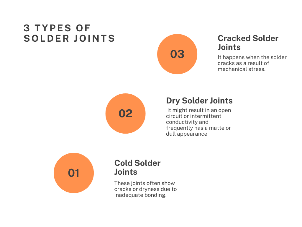
1) Cracked Solder Joint:
It happens when the solder cracks as a result of mechanical stress. There is an intermittent electrical connection as a result of the pin becoming partially removed. This problem is made worse by heavy components and frequent board movement. In travel, CRT monitors frequently exhibit this. It is possible to lessen vibrations and avoid cracks by using padded crates.
2) Dry Solder Joint:
A weak connection is the outcome of inadequate solder in a dry solder joint. It might result in an open circuit or intermittent conductivity and frequently has a matte or dull appearance. When the solder doesn't completely wet the junction while cooling, this problem arises.
3) Cold Solder Joint:
These joints often show cracks or dryness due to inadequate bonding. These joints display a dry or cracked appearance when they malfunction. They are challenging and require immediate care in order to provide dependable PCB assembly and performance.
Best Techniques for Identifying Cold Solder Joints
Visual Inspection:
This technique looks for symptoms such as dull, gritty, or broken solder by utilising a spotlight, magnifying glass, or microscope. Benefits include ease of usage and quick results. One of the limitations is that it can be challenging to find problems in tiny joints or under parts.
Testing using Multimeters:
Multimeters are used to test continuity and resistance. A higher-than-expected result in resistance mode suggests a possible cold joint. A bad connection is indicated by a silent beep in continuity mode. Accurate identification of electrical problems is one benefit. One of the limitations is that using a multimeter requires some level of proficiency.
Thermal imaging:
This method finds regions of the board with anomalous heat distribution by measuring temperature variations on the board. Benefits include seeing problems that the human eye cannot see. Higher expense and complexity are among the limitations.
Factors Contributing to Cold Solder Joints
- Temperature: Cold solder junctions may result from the soldering iron not being heated enough to properly melt the solder. It is advised to set the soldering iron to the recommended temperature, which is normally approximately 350°C (662°F), and to apply heat evenly.
- Solder Type: Improper or low-quality soldering might lead to inadequate bonding. Suggested Use: To make dependable connections, use flux and solder of the right quality for the particular application.
- Environmental Factors: Solder adhesion can be impacted by pollution, dust, and humidity. Suggestion: Throughout the PCB fabrication process, maintain a dry and clean workspace to avoid PCB contamination.
- Operator Skill and Experience: Inexperienced operators run the risk of using incorrect soldering procedures or misapplying heat. It is advised to spend money on practice and instruction to increase soldering abilities, which will result in higher-quality PCB assembly and dependable PCB layers.
Using a Multimeter to Test Solder Joints
Testing for Continuity:
- To check for continuity, switch the multimeter's mode to continuity. Put the test probes in contact with the solder joint's two ends. A complete electrical path will be shown by a beep from a good joint.
- Test known good joints for comparison and make sure the multimeter is calibrated correctly.
Testing for Resistance:
- Put the multimeter in resistance mode to test for resistance. Over the solder joint, connect the probes.
- A soldered junction with low resistance typically near zero ohms should be visible.
- Expect readings close to zero for components other than resistors; higher readings may indicate a possible cold joint.
Interpreting the Data
- A healthy joint is indicated by a low resistance or continuity mode beep. High resistance or no buzzer indicates a cold solder connection.
- Rework any problematic junctions to improve the PCB production process.
Repairing Cold Solder Joints
Insufficient heating or vibration might lead to the formation of solder joints. Because of this, they are typically fixable with just a little heat applied to the joint until the solder melts and the board is firmly held in a vice. You might need to draw off extra solder because a lot of cold joints also suffer from having too much solder.
Use a lead-free solder alloy instead of your soldering iron if it seems to cool down too quickly. These solder alloys have higher operating temperatures and are often less prone to mechanical fatigue. It's important to remember that cold solder joint detection is more challenging when lead-free alloys are used. Therefore, preventing the development of cold joints in the first place is a beneficial practice.
Characteristics of the Ideal Solder Joint
1) Smooth Surface:
If the solder has flowed properly, the joint should be level and devoid of lumps or imperfections.
2) Shiny Finish:
A well-formed joint is indicated by a shiny look. Steer clear of matte or dull surfaces, as these may indicate problems such as cold soldering.
3) Complete Wetting:
To ensure a solid bond, the solder must completely cover the PCB pad and the component lead.
4) Appropriate Flow:
To fill in voids and forge a strong bond, the solder should flow uniformly across the junction.
5) Clean Connections:
For improved adhesion, make sure the surfaces to be soldered are clear of impurities and spotless.
6) Proper Temperature:
For optimal results, apply solder while heating the connection at the proper soldering iron temperature of around 350°C/662°F.
Conclusion
An increase in electrical resistance and a decrease in connection dependability can result from improper soldering, which can cause cold solder junctions. The following impacts the PCB assembly's electrical dependability in addition to its mechanical stability. Use enough melted solder, keep the soldering area clean, and provide the soldering iron with enough heat to prevent cold solder junctions. Everyone may provide a more dependable electrical assembly by taking care of these issues, which will also enhance the quality of the PCB fabrication process and the integrity of PCB layers.
%20(1).jpg)
